Design for Manufacturability (DFM) Services
ZH Precision provides professional DFM services to optimize part designs before production. Our engineers review CAD models, identify potential manufacturing challenges, and offer practical recommendations to reduce defects, lower risks, and improve efficiency.
- Geometry Optimization
- Tolerance Analysis
- Material Selection
- Manufacturing Feasibility
- Surface Finishing Compatibility
Verify Certifications On Demand:ISO 9001:2015 | IATF 16949:2016
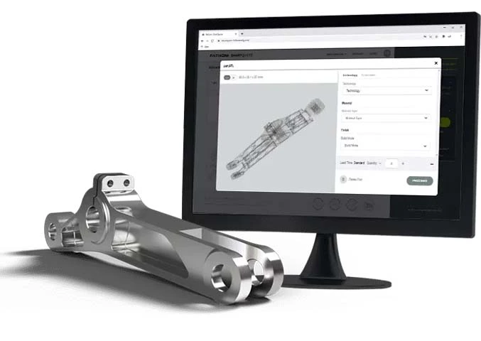
Get a Free DFM Quote
STP I SLDPRT I IPT I PRT I SAT FLES
All uploaded content is secure and confidential.
What is Design for Manufacturability (DFM)
Design for Manufacturability (DFM) is the engineering practice of optimizing part designs to make production easier, reduce costs, and improve quality. By reviewing geometry, tolerances, material selection, and assembly methods, our engineers identify potential manufacturing challenges and provide practical design improvements. Applying DFM early in development helps ensure smoother production, higher first-pass yield, and fewer delays or rework.

Why DFM is Important in Product Development
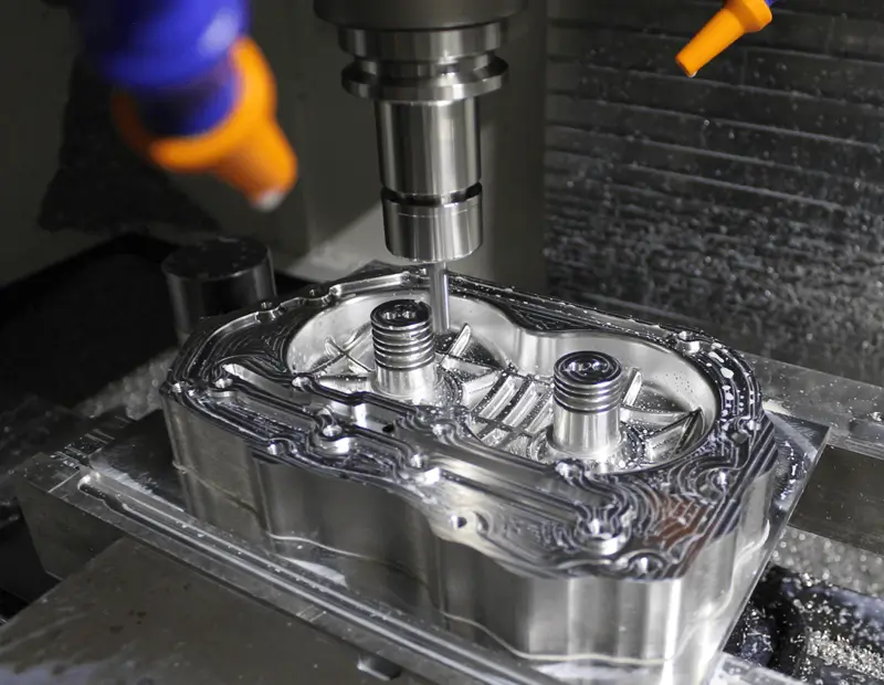
Implementing DFM early in the product development cycle is essential to prevent costly production issues and ensure high-quality parts. For CNC machining, DFM helps identify potential tool access problems, minimize complex setups, and avoid areas prone to deflection or stress concentration. In die casting, it ensures proper wall thickness, draft angles, and uniform material flow to reduce porosity, warping, and other defects. By addressing these challenges during the design phase, manufacturers can shorten lead times, reduce scrap rates, and achieve consistent part performance, ultimately saving both time and cost across the production process.
Our DFM Engineering Capabilities
ZH Precision’s engineering team leverages extensive hands-on experience to provide actionable DFM recommendations. We review CAD models for geometric complexity, wall thickness, fillets, tolerances, and assembly considerations. By combining advanced simulation tools with practical manufacturing knowledge, we identify potential production challenges early, ensuring your parts are optimized for quality, efficiency, and repeatability.
Our DFM Process
Our structured DFM process ensures your designs are fully optimized for manufacturability, cost efficiency, and high-quality production. From initial design review to prototype validation and final recommendations, each step is carefully executed to minimize errors, reduce rework, and accelerate your product’s time-to-market.
Design Review
Our engineers thoroughly examine CAD files to identify potential manufacturing challenges, such as undercuts, thin walls, tight tolerances, or complex features. This early analysis allows issues to be addressed before production, reducing errors, saving time, and supporting rapid iterations. By simulating functional performance and evaluating assembly feasibility, we help ensure your prototypes closely match final production parts.
Material & Process Evaluation
We recommend the most suitable materials and manufacturing approaches for your design, tailoring each choice to optimize performance, cost, and manufacturability. This includes early guidance on material behavior, process selection, and identification of potential defects, ensuring your parts are durable, functional, and production-ready.
Tolerance Optimization
Critical tolerances and geometric features are fine-tuned to guarantee manufacturability without compromising functionality. We consider tooling limitations, assembly requirements, and post-processing needs to create designs that are both precise and practical. This ensures parts perform reliably, maintain visual and functional quality, and are ready for market testing.
Prototype Validation
Prototypes are produced to test and validate the design, uncovering any remaining manufacturing challenges. This step verifies fit, function, and performance, providing valuable insights before moving to full-scale production. Rapid low-volume iterations help confirm design feasibility and ensure consistent quality across production runs.
Final Recommendations
Based on design reviews and prototype feedback, we provide actionable recommendations to finalize the design. This ensures parts are optimized for smooth, efficient, and cost-effective production, with high-quality finishes and reliability for large-scale manufacturing.
Design Guidelines for CNC Machining
Optimize part designs for manufacturability, focusing on wall thickness, internal corners, holes, slots, threads, and surface finishes. Following these guidelines reduces machining issues, ensures tolerance accuracy, improves tool access, and delivers reliable, production-ready components.
| DFM Guideline | Recommendations | Description |
|---|---|---|
| 🔲 Internal Corners | Radius sharp internal corners; minimum 0.5–1x end mill diameter. | Prevents stress concentration and allows smooth tool paths, improving surface finish and part durability. |
| 🧱 Minimum Wall Thickness | Aluminum ≥1.0 mm (recommended 1.5 mm+); Steel ≥1.5 mm; Plastics 1.5–2.0 mm. | Maintains structural integrity and avoids warping or machining difficulties. |
| 📏 Slot & Groove Widths | Minimum slot width = smallest end mill (typically 0.5 mm); maintain consistent width; depth-to-width ≤3:1. | Ensures machining accuracy and prevents tool breakage or deflection in deep narrow slots. |
| 🕳️ Hole & Drill Depth | Max drill depth ≤12x diameter; blind holes max 3–4x diameter; deep holes need specialized tooling. | Prevents tool breakage, ensures hole accuracy, and avoids excessive deflection in long holes. |
| ⚙️ Threads & Tapped Holes | Standard taps: M1.6–M5 depth 2–3x diameter; M6+ depth 1.5–2.5x; use inserts for thin walls. | Ensures proper engagement and avoids stripping; suitable for soft materials or thin walls. |
| ✨ Surface Finish | Target Ra 1.6–3.2 μm; fine finishing Ra 0.8–1.6 μm; polish critical surfaces. | Improves aesthetic and functional performance; aluminum easier to finish than steel or plastics. |
| 🔨 Undercuts & Complex Features | Avoid deep undercuts; if needed, use special tooling or redesign as separate assembled components. | Reduces machining complexity and cost; ensures accessibility and quality. |
| 🔪 Min End Mill Size | Minimum 0.5 mm; depth limit 1.5–2x diameter; use only when necessary. | Small tools increase cycle time and deflection risk; reserve for fine features. |
| 📐 Part Size Constraints | CNC milling up to 1000×500×500 mm (large: 2000×1000×800); turning max 500 mm diameter × 1000 mm length. | Ensure proper orientation and clamping to access all features safely. |
| 📦 Batch Volume Considerations | Prototyping 1–10 pcs; Low 10–100; Medium 100–1,000; High 1,000+. | Plan for repeatability and minimal setup changes; consider casting/forging for high volumes. |
| ⏱️ Lead Time Tips | Simple 2.5D: 1–3 days; Moderate: 3–5 days; Complex 5+ axis: 5–10+ days. | Early DFM review reduces delays by 30–50% and avoids last-minute design changes. |
Die Casting DFM Guide
Optimize die-cast parts for manufacturability, cost efficiency, and consistent quality. Key design factors include wall thickness, draft angles, fillets, hole placement, and undercuts. Following these DFM guidelines helps prevent porosity, improve mold filling, reduce tooling complexity, and deliver reliable, production-ready components.
| Guideline | Recommendation | Notes |
|---|---|---|
| 🏺 Wall Thickness | Maintain uniform wall thickness for aluminum & zinc die casting; typical 1–5 mm depending on alloy. | Avoid abrupt changes to prevent porosity and sink marks. Use ribs for reinforcement instead of thickening walls. |
| 🌀 Draft Angles | 1–3° minimum draft on vertical faces; higher for deeper parts. | Facilitates part ejection; insufficient draft can cause tearing or sticking. |
| 🔲 Fillets & Radii | Apply fillets to internal corners (0.5–1x wall thickness recommended). | Reduces stress concentration, improves metal flow, and prevents cracking. |
| ⚡ Ribs & Bosses | Ribs: 40–60% of wall thickness; Bosses: 2–3x wall thickness max. | Ensure ribs do not intersect corners at sharp angles; add small fillets at rib-base junctions. |
| 🕳️ Holes & Threaded Features | Use blind holes with 2–3x diameter depth; threads: M2–M6 standard, consider inserts for thin walls. | Avoid placing holes too close to edges or corners; taper holes for casting shrinkage compensation. |
| 🧱 Surface Finish | Target roughness: Ra 1.6–3.2 μm; polishing required for critical surfaces. | Finish quality affects secondary machining and plating; adjust design for castability. |
| 🔪 Undercuts & Complex Features | Avoid deep undercuts; if needed, use side actions or redesign as assemblies. | Complex features increase tooling cost and cycle time. |
| 📐 Part Size | Die casting feasible for small to large parts; consider mold limitations. | Oversized parts may require multiple mold sections and additional machining. |
| 📦 Batch Volume | Prototyping: 10–50 pcs; Low volume: 50–500 pcs; Mass production: 500+ pcs. | Optimize design for repeatability and minimal post-processing in high-volume runs. |
| ⏱️ Lead Time Considerations | Prototype molds: 1–3 weeks; Production molds: 4–8 weeks depending on complexity. | Early DFM review reduces mold rework and shortens overall project timelines. |
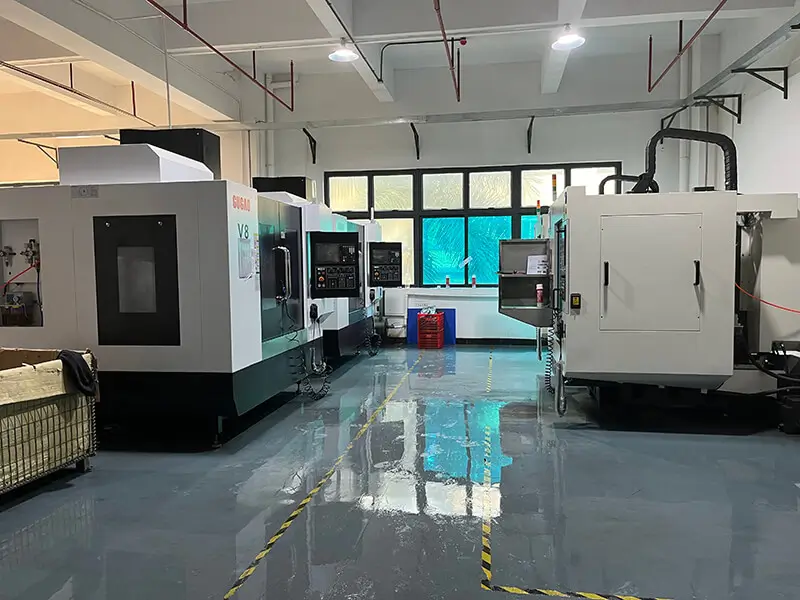
Our Manufacturing Services
ZH Precision provides reliable, flexible manufacturing services for precision parts. From prototyping to full-scale production, we ensure every component meets design specifications with consistent quality, regardless of complexity or volume.
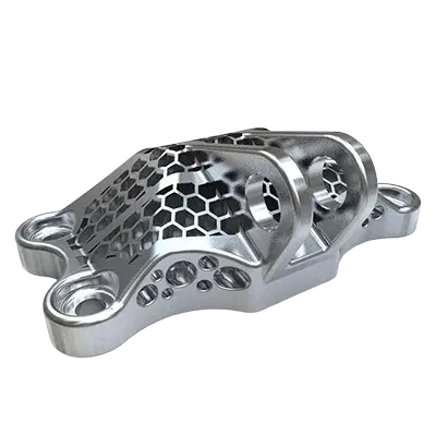
CNC Machining DFM
Evaluate wall thickness, corners, holes, threads, and surface finishes to ensure CNC-friendly parts with tight tolerances and efficient machining.
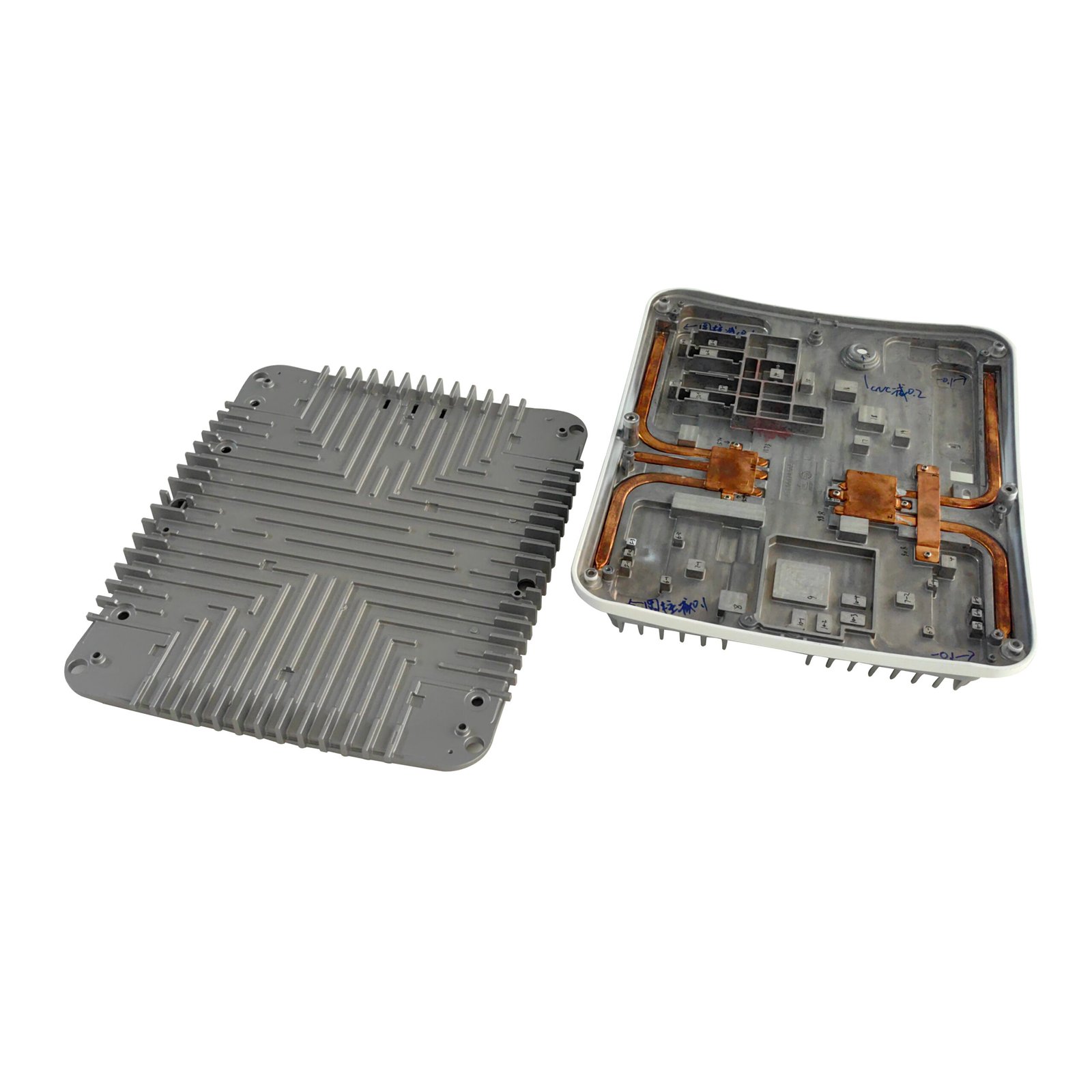
Die Casting DFM
Optimize draft angles, wall thickness, fillets, and undercuts to prevent porosity, simplify tooling, and maintain consistent casting quality.
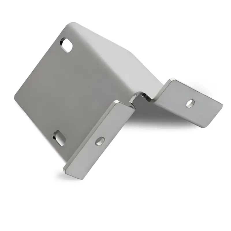
Sheet Metal DFM
Review bends, material thickness, and cutouts to minimize deformation, simplify tooling, and improve precision and repeatability.
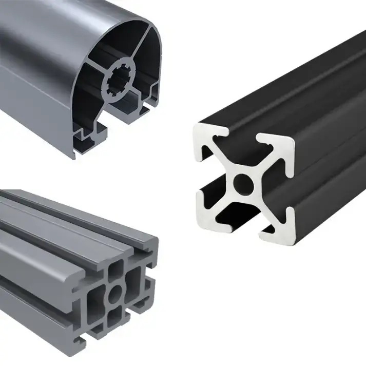
Aluminum Extrusion DFM
Assess profile geometry, wall uniformity, and tolerances to ensure efficient extrusion, reduce material waste, and support downstream machining.
Materials & Surface Finishes
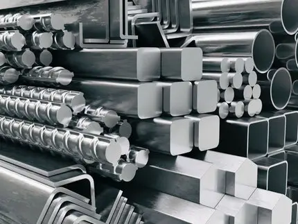
Materials
We provide a variety of metals, including aluminum, steel, stainless steel, copper, and zinc alloys.
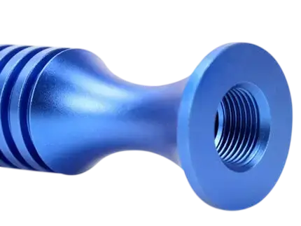
Surface Treatment
We offer superior surface finishes that enhance part durability and aesthetics for applications requiring smooth or textured surfaces.
Why Choose ZH Precision?
ZH Precision combines deep engineering expertise with advanced manufacturing capabilities to deliver precision parts that meet your most demanding specifications. Our focus on quality, reliability, and efficiency ensures reduced risk, faster time-to-market, and consistent performance. We work closely with engineering and procurement teams to provide actionable solutions, helping your projects succeed from prototype to full-scale production.
Proven Engineering Expertise
Our team brings hands-on experience and practical shop-floor knowledge to every project. By reviewing designs early, we identify potential manufacturing challenges and provide actionable recommendations that prevent costly errors and ensure manufacturability.
Precision and Quality
We implement strict quality control at every stage of production. By maintaining tight tolerances and consistent standards, we deliver components that meet functional and aesthetic requirements, giving you confidence in every part.
Efficient and Flexible Processes
From rapid prototyping to large-scale production, our workflows are designed for efficiency and adaptability. We minimize lead times, reduce rework, and handle complex geometries and varying volumes with consistent results.
Customer-Focused Solutions
We partner closely with engineers and procurement teams to understand project goals and provide tailored guidance. Our recommendations optimize designs, improve manufacturability, and streamline production, helping you save time and cost while achieving reliable results.